Danfoss VLT Aquadrive
Pump Summary
Manufacturer | Danfoss |
Models | VLT Aquadrive |
Type | VFD |
MODBUS Interface | Yes |
Support Contact | Tim More & Mitchel Lewis 209 479 1773 |
Technical Manual | See attachments below |
Photographs


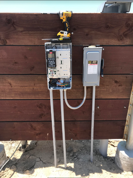
Pump Control Connections
Electrical Connections:
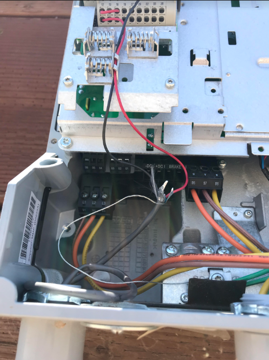
A: This is the detail showing the 2 Normally open relay wires from the Wildeye relay module connecting to the Danfoss pins 18 and 12 of the Aquadrive.
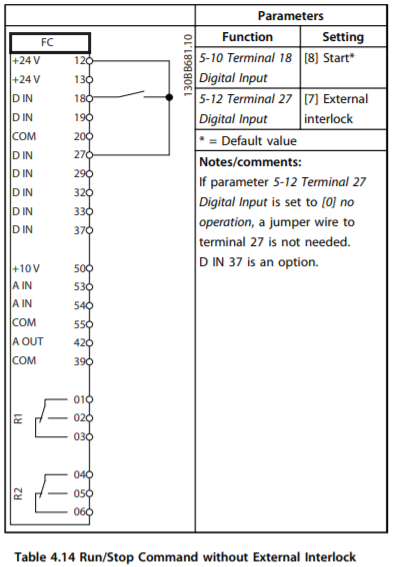
Aquadrive manual page 108 (see attachments below)

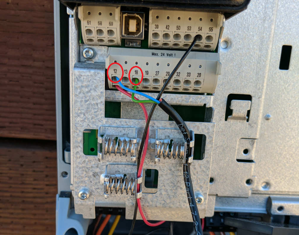
A: Here is a close-up shot how to wire the 2 relay control lines into the Aquadrive as shown below

Aquadrive Wiring Detail
Wildeye Relay control module -> Aquadrive
3-core cable:
Red | Normally Closed | Do Not Connect |
Green | COM-Common | Connects to terminal 18 |
Blue | Normally Open | Connects to terminal 12 on the Aquadrive |
For powering of the Wildeye, a 24V DC module does not fit inside the Aquadrive housing. A solar panel may be required.
Attachment of Current Switch
A current switch must be used to detect the status of the pump to alert for unexpected pump activations.
The solenoid current switch should be attached on PUMP SIDE the high current wire coming from the VFD module to the pump.
