Irrigation Scheduling Control - Configuration (Web Portal)
Configuring a client for Irrigation Scheduling control involves creating a Control Network (representing a real-world irrigation system) through the Wildeye Internal client settings and then configuring the Control Outputs.
Create a Control Network
Configure Control Outputs
This is an internal Wildeye process. Please contact Wildeye support if you need this feature.
Create a Control Network
1. | Find the client in the Clients tab of Wildeye web portal and click on the client to open the client settings page. | 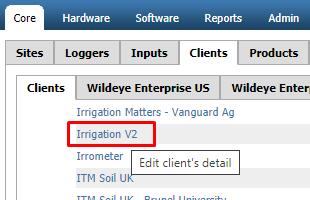 |
2. | Click on the Control Networks tab |  |
3. | Enter a name for the control network then click Add |  |
4. | Confirm the control network has been added. |  |
5. | Close the client settings window. |  |
6. | Once a control network has been defined, the Irrigation tab will be visible on Wildeye templates, allowing the customer to set up irrigation schedules. |  |
Adding & Configure Control Outputs [NEEDS UPDATE for Easy Config]
1. | Open the config inputs window of the control site by clicking the spanner icon. |  |
2. | Under Other Inputs click on the Add... button |  |
3. | From the Select Input Type: drop down list select Control - Addressable Output | 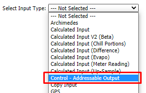 |
4. | Click the OK button to add the input |  |
5. | Click the New Input link of the newly created control output |  |
6. | Enter an input name and assign a Logical Name in the below format Output<slot> e.g. Output1 Each configured output must be set on a different slot number | 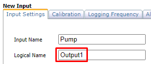 |
7. | Click Save |  |
8. | Click on link now named as per step 6 |  |
9. | Click on the Calibration tab |  |
10. | Set the address of the relay device attached to the logger using the Address drop down | 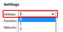 |
11. | Set the function of the device using the Function drop down. Pumps are automatically scheduled to be on while Valves are on. Valves are schedulable items. If the system is only a Pump and there are no valves, then make the Function of the Pump a valve. |  |
12. | Select the network for the control output. On a Single device all Control Outputs must be on the same network. | 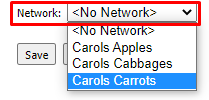 |
13. | Click Save |  |
14. | Repeat the steps to add additional valves. Each control output on a device must have its logical name set to a different slot. |  |
