
This document details how to set up a Wildeye to communicate with a Unitronics Jazz PLC.
Introduction
Unitronics PLC is a unique system that can be used as either a master or a slave depending on the requirements of the system. Wildeye loggers only work as a Modbus Master. This means that the Unitronics Jazz would need to be a Modbus slave and must be configured either as RS232 or RS485.
Configuration
Software Ladder Program Setup
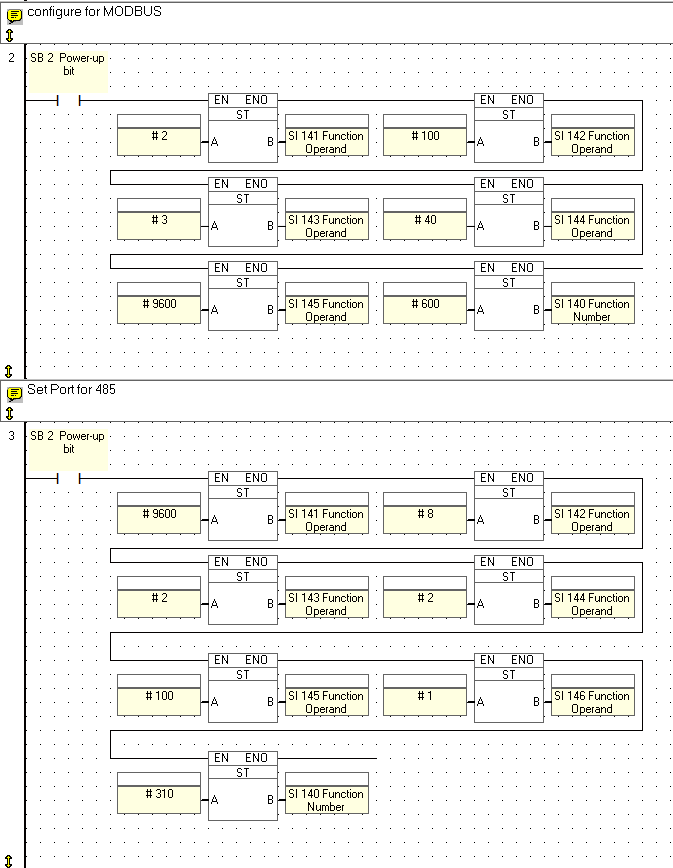
Setup the Ladder program to enable Modbus by storing values into the System Integer (SI)
|
Parameter |
SI |
Function |
|
Network ID |
141 |
Range: 0-255. This is the Network ID number of the device on the network. You can either assign an ID via an MI, or directly via a constant number. Do not assign the same ID number to more than one device. |
|
Time out |
142 |
Time out units:10 msecs; a Time out value of 100 is equal to 1 second. This is the amount of time a master device will wait for an answer from a slave. |
|
Retries |
143 |
This is the number of times a device will try to send a message. |
|
Maximum Time Delay |
144 |
Time units: 2.5 msec. This is the maximum time interval permitted between 2 messages. This should be set to 2, setting the permitted interval to 5 msecs (n x 2.5 =interval). |
|
Baud Rate |
145 |
Store the value into SI 145 to set the baud rate. Note that Jazz does not support the following baud rates: 110, 38400, 57600. In addition, ‘2’ Stop Bits is not supported. In Jazz controllers; use Function 310 to modify the default settings of an Add-on Port. Legal Baud rates are:
|
|
Call MODBUS Configuration |
140 |
This must be the final parameter stored. Storing the value 600 into SI 140 configures the controller for MODBUS. Storing the value 599 into SI 140 configures the controller for MODBUS and also enables Unitronics' PC applications to access the PLC. |
After Modbus has been setup, Configure the port by storing values into the System Integer (SI) again.
|
Parameter |
SI |
M91 |
Jazz: MJ20-RS |
Jazz: MJ20-PRG |
|
Baud Rate |
141 |
Legal Baud rates, Store value into SI 141 to set baud rate. |
||
|
|
|
|
|
|
|
Data bits |
142 |
|
||
|
Parity |
143 |
|
||
|
Hardware Flow Control |
144 |
|
RS232:
Note that in order to implement RS485, you must write 2 to SI144 |
Always write 0 |
|
Time out |
145 |
Time out units: 10 msecs; a Time out value of 100 is equal to 1 second. Legal values:
|
||
|
Stop bits |
146 |
|
2 stop bits is not supported |
|
|
COM Init |
140 |
This must be the final parameter stored. Storing the value 310 into SI 140 initializes the COM port with the new parameters. |
||
-
It should look something like this.
-
Address: 2, Baud rate: 9600, Data bits: 8, Party: None, Stop bit: 1 etc.
-
Hardware Setup
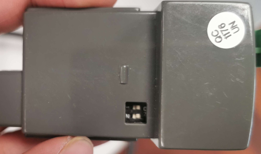
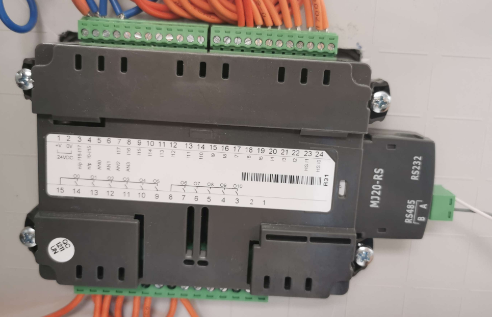
Ensure that the Wildeye cable is connected to the RS485 port of the PLC. This is usually a separate module on that would need to be purchased separately and should fit in the right hand side (from back view) of the Jazz PLC. You should be able to see the RS485 Indicator facing towards the installer. Ensure that the Termination on the RS485 module is correct and are in the same position. If this is the end of the RS485 line, then the termination switch should BOTH be in the ON position.
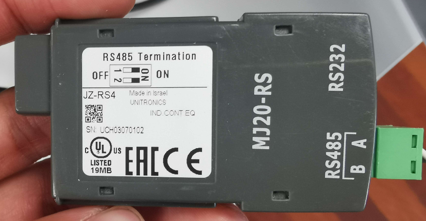
The RS485 module uses the A, B notation for the RS485. This is usually not standard and would be unique to each sensor. In this case, the A port is the D+ line and the B port is the D- line
|
Notation on the PLC |
Logger Notation |
Colour of Wire from the Logger |
|---|---|---|
|
A |
D+ |
White |
|
B |
D- |
Grey |
Setting up Inputs on the logger
There are some limitations that requires more investigation. However, currently we are able to successfully read, System Bits, System Integer, Memory Bits, Memory Integer and we were able to successfully execute a Write Register command
We have yet to attempt the Input, Output and timers. We were also unsuccessful in executing a Single Write coil.
Slave Mapping
The input setup would be based on the Ladder function code that the PLC has installed. This would be different for each PLC as each register and coil can be programmed to contain their desired value.
However, the slave mapping would be as follows.
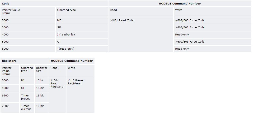
Ignoring the Modbus Command Number as it is used on the Ladder Function instead.
Input configurations
Memory bits →
-
Function: Read Coil (01)
-
Data Offset: = Memory bits address
-
Child Data Width: 8 bits
-
Child Data Type: Mask
-
Mask value (Hex): 1
Memory Integer →
-
Function: Read Holding Registers (03)
-
Data Offset: = Memory Integer address
-
Child Data Width: 16 bits
-
Child Data Type: Signed Integer
System bits →
-
Function: Read Coil (01)
-
Data Offset: = System bits address + 3000
-
Child Data Width: 8 bits
-
Child Data Type: Mask
-
Mask value (Hex): 1
System Integer (Not Verified) →
-
Function: Read Holding Registers (03)
-
Data Offset: = System Integer address + 4000
-
Child Data Width: 16 bits,
-
Child Data Type: Signed Integer
Write Register →
-
Function: Write Single Register (06)
-
Data Offset: = Memory Integer address
Stab time is not required as the PLC is powered externally.
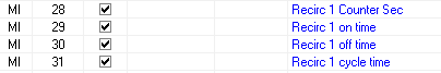
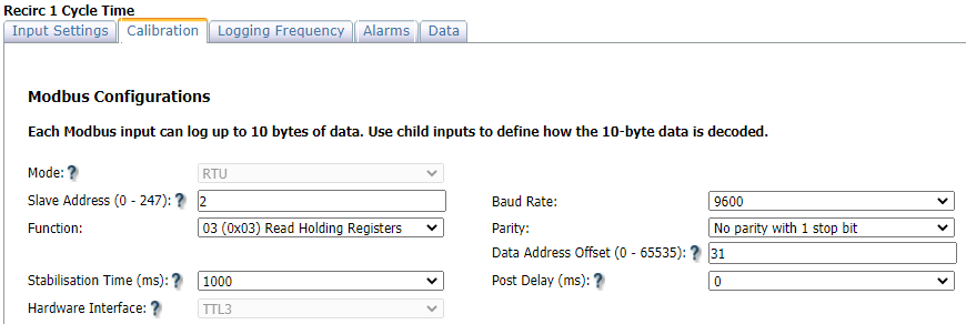
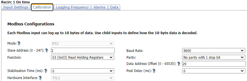
Example
Reading the MI registers 29 and 31.
References
Modbus protocol: Link
Wildeye support pages: Serial Communications (MODBUS)
Jazz: https://www.unitronicsplc.com/programmable-controllers-jazz-and-m91-series/
U90 Ladder: https://www.unitronicsplc.com/software-u90-for-programmable-controllers/
U90 Ladder help page: https://www.unitronicsplc.com/Download/SoftwareHelp/U90LadderKnowledgebase/U90_Ladder_Help.htm