
Note: These features can only be accessed by Client Admin users. Your Wildeye devices may be managed by a third party as a service.
Accessing
The Input Settings page can be accessed from the Site Page by clicking on the Input Settings icon sensor.png on each Site row.
You can also access this page when viewing any graph associated with a Site by clicking on the Input Settings icon sensor.png at the top left of the graph.
Overview
A Site can have multiple Inputs. Inputs store timeseries data associated with meters and sensors. Input settings include Logging Frequency and Calibration options.
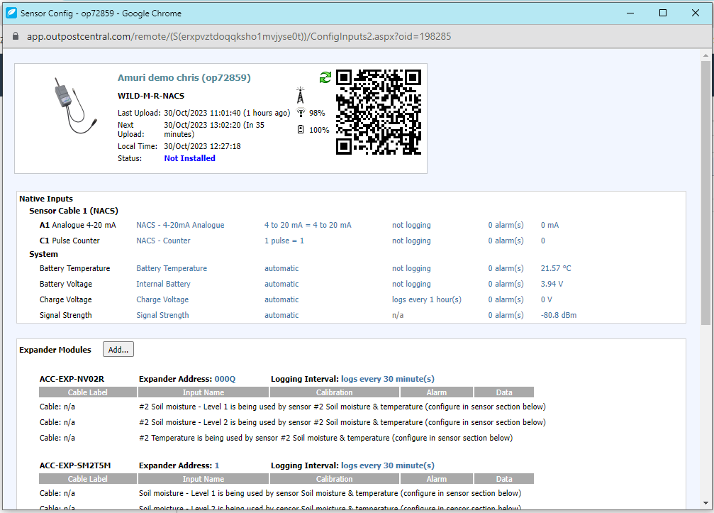
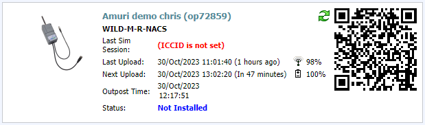
Header
The header contains the same information as the header on the Site Configuration Page.
Input Rows
Every Input attached to the site appears as a row. Each row appears in one of 4 sections:
-
Native Inputs
-
Expander modules
-
Sensors
-
Other Inputs
Each Input row has 6 Columns:
-
Input Type: The Type defines what type of sensors can be attached to the Input. (eg. Analogue, Counter, MODBUS, SDI12 etc) This cannot be changed as it is defined by the Product code of the Wildeye device in the site.
-
Input Name: The user definable name of the Input. The name can be changed by clicking the Name.
-
Calibration: The Calibration of the Input, to convert from raw units (eg volts, amps) to real-world units (eg metres, degrees Celsius). This can be changed by clicking on the calibration text. The calibration options that are available depend on the Input Type. It is easier and recommended to use the Add Sensor templating system to configure the calibration of Inputs.
-
Logging Frequency: The Logging Frequency determines how often the attached sensor is read and its result logged as time-series data. The logging frequency can be changed by clicking on the link and the Wildeye device will automatically pick up the change on its next successful connection. It is important to realize that the logging frequency of a sensor can have an impact on the battery life of the product.
-
Alarms: Multiple alarms can be configured on each Input. Clicking on the Alarms link takes you to the Alarm Settings Page.
-
Data: Access to the time series data of the Input that has been collected by the Wildeye device or data import. The last data value is shown by default. You can manipulate this data from the Data page by clicking on the link on the last data value.
Native Inputs
This section contains Inputs that are intrinsic to the Wildeye device. The available native Inputs depend on the Product code of the device. Available Input Types may include 4-20mA, 0-5V Pulse Counter, Temperature, etc. All of these Inputs are available through the Cable connectors coming out of the Wildeye device or internal to the device (System Inputs).
-
4-20mA: An industrial interface standard for sensors where the measured value is proportional to the current drawn by the sensor. You can calibrate 4-20mA Inputs with linear or piecewise calibrations. 4-20mA inputs measure an instantaneous value at the time they are logged. Some examples may be instantaneous flow rate or water level.
-
Pulse Counter: Pulse Counter Inputs log the number of counts detected since the last log. Read the Pulse Counter Channel Article for information on the electrical characteristics of the Pulse Counter.
Expander Modules
Available inputs can be expanded with some product variants by the addition of one or more Expander Modules.
Expander modules are added in software through the Add button in the expander module section, then searching or picking the expander based on Product Code. Eg ACC-EXP-NR4
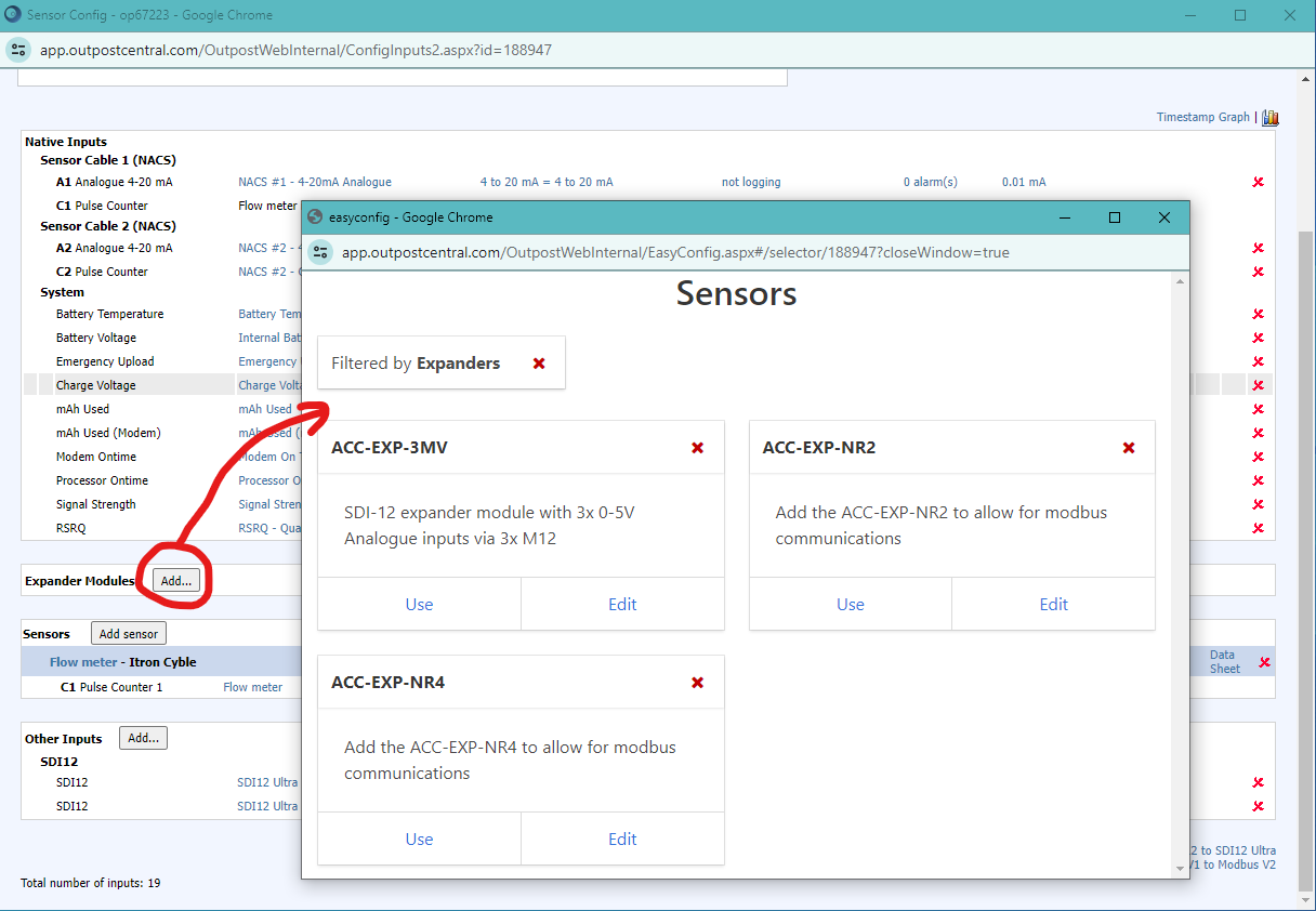
The available inputs in the software will increase according to the available Inputs of the product type of the expander module.
Expander modules have an address and a logging frequency. The logging frequency settings changes the logging frequency of all Inputs of the expander module.
Each Input on the expander module is calibrated as if it were a native Input to the Wildeye device.
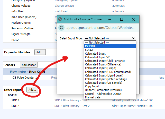
Note for adding ACC-EXP-NR4 and ACC-EXP-NR2
After adding the expander as described above, you will need to then add a MODBUS input row using the “Other Inputs” Add button.
Sensors
The Add Sensor button is a templating system that automatically configures the Inputs correctly for supported manufacturer's Meters or Sensors. Read the Add Sensor article to learn how to use this feature and see a list of currently available Sensor templates.
When Inputs are configured or added using the Add Sensor feature, they will be grouped together in this section.
Other Inputs
The Other Inputs section includes MODBUS Inputs, SDI12 Inputs, and Calculated Inputs. These are advanced features that require specialist knowledge and training to use. It is not generally necessary to add or configure these Inputs yourself as they are automatically configured when using the Add Sensor templating feature.