Inputs Setup - MODBUS Serial Communications
Modbus is a serial communication protocol developed by Modicon in 1979 for use with its programmable logic controllers (PLCs). It enables a method to transmit information over serial lines between electronic devices.
In standard Modbus network, there is a Master and a up-to 247 slaves, each with a unique Slave address from 1 to 247.
To configure a Modbus input for a supported Wildeye logger, do the following:
Click Config Sensor for the relevant site.
Click Add Input and select MODBUS.
There are two different versions of Modbus input. Modbus V1 and Modbus V2.
Modbus V1 is a legacy input type. Most of the Loggers are using Modbus V2 by default. Modbus V2 is supported by all WILD-M 4G devices, and 3G devices with PIC Firmware Version 6.2.0 and above only. The differences are as following:
Modbus V1 (legacy)
Baud rate supported - 9600
Parity supported - None
Stop bits supported - 1
Maximum of 8 bytes read
RTU mode only.
Functions 3 (Read Holding Registers) and 4 (Read Input Registers) supported
Modbus V2
Baud rate supported - 2400, 4800, 9600, 19200
Parity - None, Odd or Even
Stop bits supported - 1 or 2
Maximum 10 bytes read
Functions 1 (Read Coils), 2 (Discrete Inputs), 3 (Read Holding Registers) and 4 (Read Input Registers) supported
Parent Input Configuration

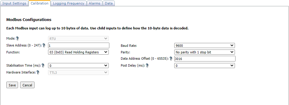
Mode - Only RTU mode is supported. ASCII mode is not supported.
Slave Address - Address of the Modbus slave. Valid address are 1 - 247 as per specification. 0 is for broadcast request to multiple slaves if present.
Function - Modbus Function code.
Data Address Offset - This field indicates the Modbus register address. Valid range: 0 - 65535.
Write Value - This indicates the 16-bit value (Valid range: 0 - 65535) to be written at given address. This field will be visible only if Function is 6.
Baud Rate - UART baud rate.
Parity - Parity for UART comms.
Stabilization Time - The time required for the sensor to stabilize after power-up and comms can start. The time is in 50ms resolution. Valid range: 0 - 12.75 seconds.
Post Delay - The time delay before sending the next command to the same device. The time is in 50ms resolution. Valid range: 0 - 12.75 seconds.
Hardware Interface (Deprecated) - This field is editable only from PIC FW 6.4.3. For logger with older FW or logger without the new expansion board, logger will ignore this field. This is required only for logger with the new expansion board which can support Modbus over multiple HW interfaces:
TTL3
TTL5
RS232
RS485
Based on the child input configuration, only a maximum of 10 bytes can be read per input.
Child Input Configuration
On the Inputs page, Select "Child Inputs" for the respective parent Modbus input

You will get a pop-up page and Select "Add Child Input"

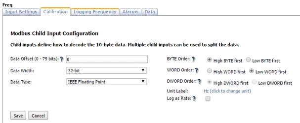
Click on the new Child Input link and another pop-up page will appear as below:

Data Offset - Bit index to the data received
Important
For Modbus Function 3, 4, 6 and 16 each address corresponds to a 16-bit data.
For Modbus Function 1, 2 and 5, each address corresponds to 1-bit of data.
Data Configuration
Data Width: Width of the data. Supported range: 8-bit, 16-bit, 32-bit, and 64-bit.
Data Type: Data interpretation. Supported Range: Signed Integer, Unsigned Integer, IEEE Floating Point, and Mask.
Only 32-bit IEEE float is supported.
Mask: It will apply the "Mask Value" on the defined "Data Width". This method avoids using Calculated Input on the data.
It is used to retrieve the desired bits (implicit right shift by leftmost zeros in the "Mask Value").
Examples:
If Mask Value is FF and Data Width is 8, it will return the whole 8-bit value.
If Mask Value is F0 and Data Width is 8, it will return upper 4 bit value (value will right-shifted by 4 bits after masking with F0).
Data Ordering:
BYTE Order: This will swap the bytes within a 16-bit data. Disabled if "Data Width" is 8-bit.
WORD Order: This will swap the words (16-bit) within a 32-bit data. Disabled if "Data Width" is less than 32-bit.
DWORD Order: This will swap the dwords (32-bit) within a 64-bit data. Disabled if "Data Width" is less than 64-bit.
Logging Configuration
Log as Rate:
If disabled, raw Modbus values will be inserted into the database.
If enabled, the difference of the Modbus values will be inserted into the database.
Maximize data read by combining values:
Wildeye loggers can support a total of 13 user inputs.
To maximize Modbus read values, loggers can be configured to read combined values from consecutive addresses.
Logger Input Limitations:
Logger has a restriction of maximum 13 inputs.
PIC Modbus: a read maximum of 104 bytes with the bytes to be read per input from consecutive addresses.
PIC Modbus V2: a read maximum of 130 bytes with the bytes to be read per input from consecutive addresses.
Typical Setup
Typical setup would be for customers to read from each consecutive address as an input each. This can be set up so we read both addresses with 1 input. For example:
Modbus input reads 2 bytes, and customer needs to extract 1 byte each.
The higher byte depicts Flow and lower byte depicts Temperature.
Use "Calculated Input" to process each byte via a VB script. VB knowledge is required.
Create a "Calculated Input" named Flow. Add VB script to extract only the Higher byte.
Create a "Calculated Input" named Temperature. Add VB script to extract only the Lower byte.
See VB example for more details.
