Supported Meter/Sensor Input Channel Types
A Wildeye has 1 or 2 physical cables containing one or more channels for attaching meters/sensors.
Expander modules allow additional channels and non-native channel types to be added to a Wildeye. An expander module has between 1 and 4 physical cables each containing one or more channels.
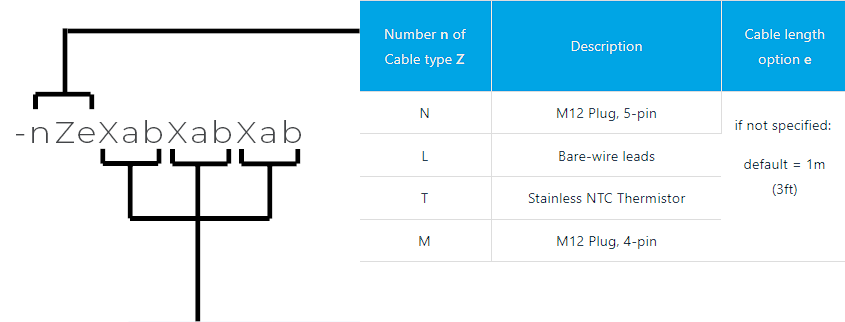
For both Wildeyes and Expander modules, the type of the cable and the channels contained inside it are defined by the cable codes.

Wildeye Channel Interface Details
Channel Type | Wildeye Channel Interface Details | Channel Availability | Channel Description |
Counter | C | Wildeye Native Only | The Counter Input is designed to accept pulse count inputs from flow meters, power meters and other sensor types that output dry contact or transistor style counts. For further details see Pulse Counter Channel Details |
4-20mA | A | Wildeye Native or Expander | 4-20mA Analogue Channel is a single-ended input designed to accept analog signals from level, pressure, temperature, and other sensors that use the 4-20mA or 0-20mA standard. An onboard 12v "Switched Power Output" can be used to power sensors - or choose an alternative voltage option. Wildeye supports 2, 3 and 4-wire 4-20mA wiring. For further details see 4-20mA Analogue Channel Details |
0-5V | V | Expander Only | Wildeye supports up to 4 x 0-5V output sensors through the use of an expander module. An onboard 12v "Switched Power Output" can be used to power sensors, or choose an alternative voltage option. For further details see Voltage Channel Details |
SDI12 | S | Wildeye Native Only | SDI12 is a standard digital interface protocol for environmental monitoring sensors. Wildeye powers sensors with onboard 12v "Switched Power Output". Wildeye software supports the attachment of up to 12 x SDI12 (the exact number may be limited by power consumption of the attached sensors). For further details see SDI-12 Channel Details |
Serial (MODBUS) | R | Wildeye Native Only | Wildeye supports RS232, RS485 and TTL hardware interface options. Note that the data protocol used on top of these hardware interfaces is specified separately. Wildeye supports MODBUS data protocol out of the box. For other supported protocols please inquire with Wildeye. RS232 and TTL interfaces can only attach to a single meter/sensor. RS485 can attach to multiple meters/sensors. For further details see Serial Communications (MODBUS) |
Resistance | O | Expander Only | Wildeye supports up to 4 x 0-10K resistance inputs through the use of an expander module. Multiple expander modules can be attached to a Wildeye. |
Watermark | W | Expander Only | Wildeye supports up to 3 x "Watermark" standard soil tension sensors through the use of an expander module. Multiple expander modules can be attached to a Wildeye. |
Cables:
Cable with M12 waterproof plug end, 5-pin (code = N)
Cable with bare-wire leads (code = L)
Cable with stainless steel NTC thermistor (code = T)
Cable with M12 waterproof plug end, 4-pin legacy type (code = M)
Channels:
Each cable can contain one or more channels of the following types:
SDI12 channel (code = S)
4-20mA / 0-20mA Current Loop channel (code = A)
Voltage Input channel (code = V)
Counter channel (code = C)
Serial Communication Channel (code = R)
Resistance channel (code = O)
Watermark soil tension channel (code = W)
Dry-contact "Digital" channel (code = D)
Channel Options:
Each channel type can have different channel options defined by a number appearing after the channel code. If there is no number, it means the default options are chosen.
A second number after a channel code letter indicates the number of instances of that channel type in the Cable. If there is no second number, it indicates a single channel of that type in the cable.
Example Cable Codes:
-NACS: Cable Type N (M12 Plug, 5-pin), containing A (4-20mA), C (Counter), and S (SDI12) channels. No special option numbers follow any of the channels codes.
-3LW: Cable Type L (Bare-wire leads) containing channel type W (Watermark). There are 3 of these cables.
-NV03: Cable Type N (M12 Plug, 5-pin), containing 3 x V (0-5V) channels. The option number "0" after the V indicates no special options for the V channels, but the "3" indicates there are 3 x V channels present on this cable.

Channel X | Description | Channel X | Description | Channel Option a | Max Channels b per Cable Z |
S | S | N/A | Max 1 | ||
A | A | 0 =12V Switch Power (default) | Max 3 | ||
V | V | 0 = 0-5V with 12V SPO (default) | Max 3 | ||
C | C | 0 = Default, Debounced Input | Max 2 | ||
R | R | 2= RS232 | Max 1 | ||
O | Resistance / Ohms | O | Resistance / Ohms | 0 = Default, 10K range | Max 4 |
W | Watermark | W | Watermark | N/A | Max 1 |
D | Digital / Dry Contact | D | Digital / Dry Contact | N/A | Max 4 |
